If you’re an engineer, drafter, or buyer of CAD services in Australia, understanding the difference between 2D and 3D drawings is fundamental. The two formats serve different purposes — and choosing the right one for your project affects cost, accuracy, and what your manufacturer can do with the file.
Quick Answer: 2D vs 3D Drawings
| 2D Drawing | 3D Drawing / Model | |
|---|---|---|
| Dimensions | Length + width (flat) | Length + width + depth (volumetric) |
| Views | Front, top, side (orthographic) | Full 3D — rotate, pan, zoom any angle |
| File formats | DWG, DXF, PDF | STEP, IGES, STL, SLDPRT, IPT, RVT |
| Main software | AutoCAD (2D), MicroStation | SolidWorks, Inventor, CATIA, Revit |
| Mass/volume data | ❌ None | ✅ Yes (solid models) |
| Use in manufacturing | CNC code, fabrication, shop floor | Simulation, FEA, 3D printing, CNC |
| File size | Small | Larger (especially assemblies) |
| Australian standard | AS/NZS 1100 — all drawings | AS/NZS 1100 + ISO 16792 (3D annotation) |
What Is a 2D Drawing?
A 2D drawing represents an object on a flat plane using two dimensions: length and width. It communicates the geometry of a part using multiple orthographic views — typically front, top, and side — laid out on a drawing sheet per AS/NZS 1100.
Every manufactured part still needs a 2D drawing (also called an engineering drawing or technical drawing) to define tolerances, surface finish, material, and manufacturing notes — information that 3D models don’t carry natively.
What 2D drawings include
- Orthographic views (front, top, side, auxiliary)
- Dimensions and tolerances (bilateral, unilateral, GD&T)
- Surface finish callouts (Ra values)
- Material and treatment specifications
- Title block (part number, revision, scale, drafter)
- Section and detail views
- Weld symbols (AS 2812 / AS/NZS 2980)
- Bill of materials (for assemblies)
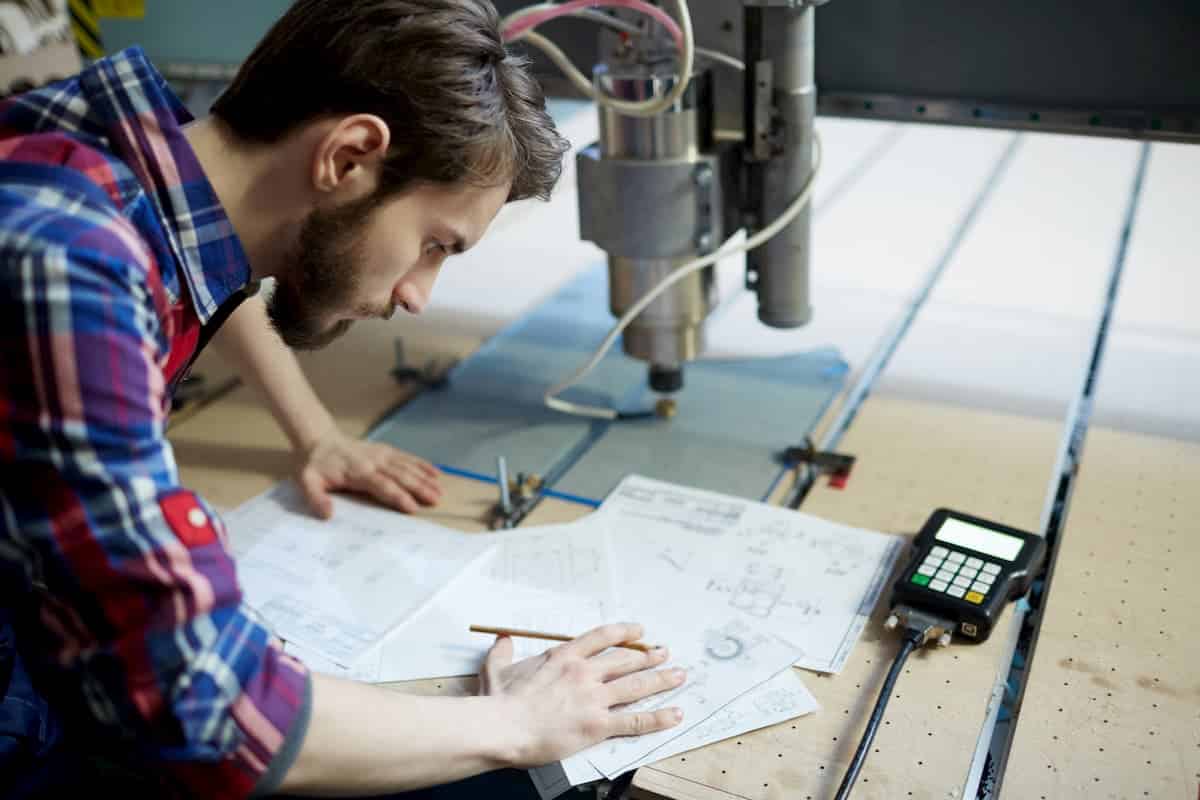
When to use 2D drawings
- Workshop fabrication and machining — the shop floor works from 2D drawings
- Structural steel detailing (AS 4100)
- Architectural construction documentation
- Electrical schematics and wiring diagrams
- Council and building permit submissions
- MEP coordination drawings
- Converting legacy paper drawings to CAD
")
What Is a 3D Drawing (3D CAD Model)?
A 3D drawing — more accurately called a 3D CAD model — represents an object in three dimensions with length, width, and depth. Unlike 2D drawings, a 3D model lets you rotate, pan, and inspect the part from any angle.
There are three types of 3D CAD models, each with different capabilities:
1. Wireframe models
The simplest 3D format — stores only vertices and edges, no surfaces or mass. Lightweight but hard to visualise and can’t be used for analysis. Mostly used as a stepping stone or reference geometry.
2. Surface models
Adds outer surfaces to the wireframe — the model looks solid but has zero thickness and no mass. Surface models can shade, colour, and texture for visualisation. Used heavily in industrial design, automotive body styling, and any complex freeform geometry. Common software: CATIA, Rhino, Alias.
3. Solid models
The most capable 3D format — stores vertices, edges, surfaces, AND mass. A solid model encloses a volume and contains material properties, enabling:
- Mass properties — weight, centre of gravity, moment of inertia
- FEA / stress analysis — simulate loads and predict failure points
- Motion simulation — verify assemblies move correctly
- 3D printing — export STL direct from the model
- CNC machining — generate toolpaths from the solid
- Rendering — photorealistic product images
The dominant solid modelling packages in Australia are SolidWorks, Autodesk Inventor, CATIA, Siemens NX, and Revit (for architecture/BIM).
")
2D vs 3D Drawings: Which Do You Need?
| Your project need | What you need |
|---|---|
| Part to be machined or fabricated by a workshop | 2D drawing (with tolerances + title block) |
| Part to be 3D printed | 3D solid model (STL export) |
| Structural steel — workshop fabrication | 2D shop drawings (per AS 4100) |
| Architecture — council submission | 2D drawings (floor plans, elevations, sections) |
| Architecture — client presentation or marketing | 3D render from Revit or SketchUp |
| Mechanical assembly — check fit before making | 3D assembly model with motion simulation |
| Product design — stress test before prototyping | 3D solid model with FEA analysis |
| Conversion — paper drawing to CAD | 2D DWG (and optionally a 3D model) |
| MEP / building services | 2D and/or 3D Revit MEP model |
Do 2D and 3D Drawings Work Together?
Yes — and this is how most professional CAD workflows operate. The 3D solid model is built first, then 2D drawings are generated from it automatically. When the 3D model changes, the 2D drawing updates. This model-based design (MBD) approach eliminates the risk of drawings being out of sync with the model.
The 3D model handles: design intent, simulation, interference checking, and CNC programming. The 2D drawing handles: tolerances, surface finish, annotations, and workshop instructions. Both are needed for a complete deliverable.
File Formats: 2D vs 3D
| Format | Type | Used for |
|---|---|---|
| DWG / DXF | 2D (and 3D wireframe) | AutoCAD drawings — most common 2D exchange format |
| 2D (print/view) | Sharing drawings for review and council submission | |
| STEP (.stp) | 3D solid / surface | Universal 3D exchange — works in any CAD software |
| IGES (.igs) | 3D solid / surface | Older exchange format — still widely used |
| STL | 3D surface (mesh) | 3D printing only |
| SLDPRT / SLDASM | 3D solid (SolidWorks) | SolidWorks native parts and assemblies |
| IPT / IAM | 3D solid (Inventor) | Autodesk Inventor native |
| RVT | 3D BIM (Revit) | Architecture, structural, MEP building models |
What is the main difference between 2D and 3D drawings?
A 2D drawing shows an object on a flat surface using two dimensions (length and width) — typically as orthographic views (front, top, side). A 3D drawing adds depth, creating a volumetric model you can view from any angle. 2D drawings define tolerances, surface finish, and manufacturing instructions. 3D models contain mass, volume, and enable simulation, rendering, and 3D printing. In practice, both are used together: the 3D model is built first, then 2D drawings are generated from it.
Which is better for manufacturing — 2D or 3D drawings?
Manufacturing requires both. The workshop needs a 2D drawing with explicit tolerances (e.g. ±0.05mm), surface finish callouts (Ra 1.6), material specifications, and title block — information that 3D models don’t fully communicate on their own. The 3D model is used to generate CNC toolpaths, check fit in assemblies, and 3D print prototypes. Sending only a 3D model to a workshop without a 2D drawing is risky because the machinist has no tolerance or finish guidance.
What CAD software creates 2D drawings vs 3D models?
For 2D drawings: AutoCAD is the industry standard, used by most Australian engineers and drafters. MicroStation is common in infrastructure and government. For 3D solid modelling: SolidWorks and Autodesk Inventor dominate Australian manufacturing and fabrication. CATIA is used in aerospace and automotive. Revit handles architecture, structural, and MEP in 3D (BIM). Most 3D packages generate 2D drawings directly from the model — SolidWorks produces DWG/PDF drawing sheets, Inventor produces idw/DWG, Revit produces A-series sheet sets.
Is a 3D model the same as a 3D drawing?
Not exactly. A 3D drawing usually refers to a 2D representation that conveys 3D depth — like an isometric view or a perspective sketch on paper. A 3D model is a digital object with actual three-dimensional geometry stored in a CAD file (STEP, SLDPRT, IPT, etc.). In engineering practice, ‘3D drawing’ is informally used to mean a 3D CAD model. The distinction matters when specifying deliverables: a ‘3D model’ in STEP format is a specific, unambiguous request; a ‘3D drawing’ could mean different things to different people.
Need 2D drawings, 3D models, or both for your Australian project? ASTCAD’s drafting team works in AutoCAD, SolidWorks, Inventor, Revit, CATIA and more — delivering AS/NZS 1100-compliant drawings and STEP/IGES models to any specification. Get a free quote.