Designing 3D Mechanical Parts in AutoCAD is an essential skill for engineers, designers, and manufacturers who want to bring their ideas to life with precision and efficiency. AutoCAD, developed by Autodesk, is one of the most widely used CAD software applications for creating detailed mechanical drawings, models, and assemblies. Whether you’re designing machine components, tools, or industrial equipment, AutoCAD provides a robust platform to create accurate 3D models that streamline prototyping and manufacturing processes.
In this guide, we’ll walk through the basics of designing 3D Mechanical Parts in AutoCAD, share practical tips, and answer some frequently asked questions.
Why Use AutoCAD for 3D Mechanical Parts?
AutoCAD is not just for 2D drafting—it’s a powerful tool for 3D modeling as well. Here’s why it’s ideal for mechanical part design:
- Precision and Accuracy: AutoCAD allows you to create models down to the finest detail, ensuring every hole, slot, and dimension aligns perfectly.
- Compatibility: Files can be exported in various formats (e.g., .STL, .STEP, .IGES), making it easy to integrate with 3D printers, CNC machines, and other CAD/CAM software.
- Visualization: 3D models provide a realistic preview of mechanical parts, helping to detect design flaws before production.
- Efficiency: The parametric and feature-based design tools allow for quick modifications, saving time in the design iteration process.
Steps to Design 3D Mechanical Parts in AutoCAD
1. Start with a Concept
Before diving into AutoCAD, have a clear idea of the part you want to design. Gather sketches, technical requirements, and measurements. This will help guide your 3D modeling process.
2. Set Up the AutoCAD Workspace
- Switch to a 3D Modeling workspace by going to the workspace settings in AutoCAD.
- Familiarize yourself with the 3D tools panel: Extrude, Revolve, Sweep, Loft, and Boolean operations (Union, Subtract, Intersect).
3. Create a 2D Sketch
Every 3D model starts with a 2D sketch:
- Use commands like LINE, CIRCLE, RECTANGLE, and POLYLINE to draw the base profile of your part.
- Ensure that dimensions are accurate using the DIMENSION tool.
4. Convert 2D Sketches into 3D Models
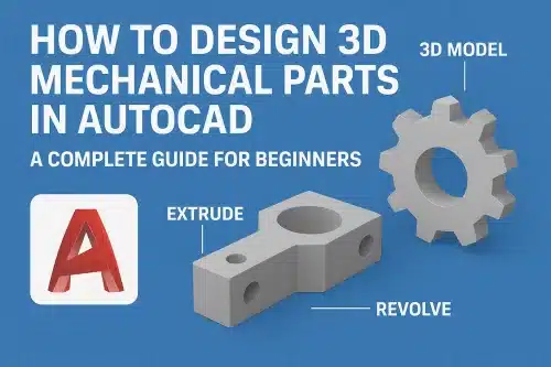
- EXTRUDE: Turn a closed 2D profile into a 3D solid by pulling it along the Z-axis.
- REVOLVE: Rotate a 2D sketch around an axis to create cylindrical or spherical parts (useful for gears, pulleys, or shafts).
- SWEEP and LOFT: Create complex parts by sweeping a profile along a path or lofting between multiple shapes.
5. Modify 3D Models
Once you’ve created the basic shape, refine it with modification tools:
- FILLET and CHAMFER: Add smooth edges or beveled corners.
- SHELL: Hollow out parts to reduce weight.
- BOOLEAN operations: Combine or subtract solids to create complex designs.
6. Add Details
Mechanical parts often require features like holes, threads, or slots. Use the following:
- HOLE or CYLINDER tool for drilled holes.
- ARRAY tool to create repetitive features like bolt patterns.
- PRESSPULL tool to cut shapes into surfaces.
7. Apply Materials and Rendering
Assign materials (metal, plastic, etc.) to your part for realistic visualization. AutoCAD’s rendering tools help you see how your design will look in real-world conditions.
8. Check and Export Your Design
- Use MEASURE tools to verify dimensions.
- Export in formats like .STL for 3D printing or .STEP/IGES for manufacturing.
Best Practices for Designing 3D Mechanical Parts in AutoCAD
- Start Simple: Break down complex parts into smaller, simpler shapes before combining them.
- Use Constraints: Apply geometric and dimensional constraints to maintain design accuracy.
- Organize with Layers: Assign different parts or features to layers for easier editing.
- Regularly Save Versions: Keep backups as you progress to avoid losing work.
- Simulate Movements: If designing assemblies, test how parts move and fit together.
Common Applications of 3D Mechanical Parts in AutoCAD
- Automotive components (gears, engine parts)
- Industrial machinery and equipment
- Aerospace components
- Consumer products (electronics housings, tools, etc.)
- Prototypes for 3D printing and CNC machining
Final Thoughts
Designing 3D Mechanical Parts in AutoCAD allows engineers and designers to create highly accurate and functional models that bridge the gap between concept and reality. By mastering the core 3D tools, understanding best practices, and practicing regularly, you can unlock AutoCAD’s full potential in mechanical design.
Whether you are a beginner or a professional, AutoCAD equips you with the tools to design, visualize, and prepare your mechanical parts for real-world applications.
Can beginners design 3D Mechanical Parts in AutoCAD?
Yes! AutoCAD is beginner-friendly, and with practice, you can quickly learn to design simple parts before progressing to more complex mechanical assemblies.
What file format should I use for 3D printing mechanical parts?
For 3D printing mechanical parts, we recommend using .STL format as it’s widely supported by most Australian and international 3D printing services. However, if you’re sharing designs with manufacturers or need to preserve complex geometry, .STEP or .IGES formats are superior choices as they maintain full design intent. We suggest confirming your service provider’s preferred format before finalising your export.
How do I ensure accuracy in my 3D models?
We recommend enabling SNAP and GRID settings to maintain precision throughout your 3D modeling process, then apply geometric constraints during sketching to lock relationships between elements. Always verify dimensions against your design specifications and Australian standards before extruding or modifying features. Double-check measurements using the DIMENSION tools, and consider using our drafting templates that align with local engineering conventions to ensure your models meet project requirements.
Can AutoCAD simulate stress or load on mechanical parts?
AutoCAD itself doesn’t have built-in stress simulation, but as an Australian CAD drafting firm, we recommend exporting your models to Autodesk Inventor or Fusion 360 for comprehensive stress analysis and FEA testing. Many of our clients use these integrated tools for compliance with Australian engineering standards before manufacturing.
Is AutoCAD better than SolidWorks or Fusion 360 for mechanical design?
AutoCAD excels at 2D drafting and basic 3D modeling, making it ideal for many Australian engineering projects and construction documentation. However, SolidWorks and Fusion 360 offer superior parametric modeling, assembly capabilities, and simulation tools better suited for complex mechanical design. We recommend AutoCAD for detailed technical drawings and compliance with Australian Standards, while considering specialist software for advanced product development requiring extensive testing and iteration.