Sheet metal design is a vital skill in mechanical and industrial engineering, enabling the creation of durable and functional parts used in products ranging from electronics to automotive and aerospace systems. For CAD beginners, understanding how to approach sheet metal design for fabrication can make the difference between a concept that works in theory and one that performs reliably in the real world.
In this tutorial, we’ll walk you through the key steps of designing for sheet metal fabrication using CAD tools. We’ll also provide helpful tips to avoid common pitfalls and ensure your designs are both manufacturable and cost-effective.
What Is Sheet Metal Design?
Sheet metal design involves creating flat 2D or 3D models that can be fabricated into parts by processes like bending, cutting, punching, and welding. Unlike standard 3D modeling, sheet metal design requires you to account for factors like bend allowances, material behavior, and tool constraints.
CAD software like SolidWorks, AutoCAD, and Fusion 360 often includes dedicated sheet metal modules, making it easier to unfold designs and prepare them for manufacturing.
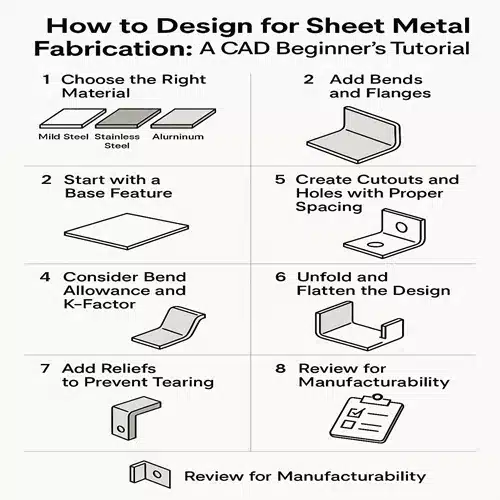
Step-by-Step Beginner’s Guide to Sheet Metal Design
1. Choose the Right Material
Before you start designing, understand the properties of your sheet metal material. Common materials include:
- Mild steel – affordable and easy to form
- Stainless steel – corrosion-resistant but harder to bend
- Aluminum – lightweight and corrosion-resistant
- Copper and brass – used in decorative and electrical applications
Each material has different thicknesses, minimum bend radii, and strength characteristics, all of which affect your design.
2. Start with a Base Feature
In CAD, a base flange/tab is typically the starting point. This flat profile acts as the foundation for your design.
- Begin with a 2D sketch on the top plane.
- Extrude it to the desired thickness of your sheet.
- Use the Sheet Metal toolset to convert it into a sheet metal part (if not already using a dedicated sheet metal template).
3. Add Bends and Flanges
Using the CAD software’s bend or flange tools, add the necessary folds and edges to your design.
Key bend considerations:
- Maintain a minimum bend radius (typically equal to the sheet thickness).
- Avoid bending too close to holes or edges, as this may lead to cracking or deformation.
- Use uniform bend directions wherever possible to simplify the manufacturing process.
4. Consider Bend Allowance and K-Factor
When metal bends, it stretches and compresses. This needs to be accounted for in your flat pattern layout using bend allowance and K-factor.
- Bend Allowance: The arc length of the bend, which must be added to the flat length.
- K-Factor: A ratio that defines how material stretches during bending (commonly between 0.3 to 0.5 for most materials).
Modern CAD software can calculate this automatically when you input the material and bend radius.
5. Create Cutouts and Holes with Proper Spacing
Holes, slots, and cutouts are common in sheet metal parts, but their placement is crucial.
- Keep holes at least 2x the material thickness away from bends.
- Ensure minimum hole diameter is not smaller than the thickness of the material to avoid deformation.
- Use standard hole sizes wherever possible for tooling efficiency.
6. Unfold and Flatten the Design
Once your model is complete, use your CAD software to generate the flat pattern.
This allows you to:
- Export DXF files for laser cutting or CNC punching.
- Validate the manufacturability of your part.
- Check for interference or overlap in bends or flanges.
7. Add Reliefs to Prevent Tearing
When bending corners or edges, bend reliefs help avoid tearing or warping.
- Use rectangular or obround reliefs where necessary.
- Most CAD tools offer preset relief options you can apply automatically.
8. Review for Manufacturability
Before finalizing your design:
- Review for minimum bend radii.
- Ensure standard tooling can produce the part.
- Minimize the number of bends and tooling operations where possible.
Sending your design to a fabricator for feedback can help optimize it further.
Best CAD Tools for Sheet Metal Design
- SolidWorks Sheet Metal Module – Highly intuitive and widely used in industry.
- AutoCAD Mechanical – Great for 2D layouts and DXF file exports.
- Fusion 360 – Good for beginners and hobbyists, with built-in flat pattern support.
- Onshape – Cloud-based and great for collaboration.
Conclusion
Mastering sheet metal design is a valuable skill for any aspiring CAD designer. By understanding the basics—material selection, bending rules, allowances, and proper CAD workflow—you can create parts that are not only functional but also easy and cost-effective to manufacture.
As you grow more confident with your CAD software, you’ll be able to create more complex designs, improve production efficiency, and reduce waste in your fabrication projects.
What is the minimum bend radius in sheet metal design?
The minimum bend radius typically equals the material thickness but may vary based on material type and your specific fabrication process. We recommend checking with your local Australian sheet metal fabricator or supplier, as minimum bend radii can differ between workshops depending on their equipment capabilities. Always consult the material manufacturer’s guidelines and your fabricator’s specifications before finalising your CAD design to avoid costly revisions.
Why is bend allowance important in sheet metal design?
Bend allowance is crucial because it accounts for the material stretch that occurs during the bending process, ensuring your flat patterns are accurate for fabrication. At ASTCAD, we’ve found that overlooking this causes costly errors when your sheet metal parts don’t fit together properly. Different materials and thicknesses require different allowances, which is why we recommend consulting Australian Standards or your fabricator’s specifications. Getting this right means your designs manufacture first time, saving time and money on your project.
How do I prevent tearing near bends?
To prevent tearing near bends, we recommend using bend reliefs, which are small notches cut into the material at the inside corner of bends. You should avoid placing holes or slots too close to bend lines, as this weakens the material in that area. Our experienced drafters typically maintain a minimum distance of at least two times the material thickness from any bend, and we always specify appropriate relief sizes in our CAD drawings to ensure your fabricator can produce quality parts without material failure.
Can I use regular 3D CAD tools for sheet metal design?
Yes, you can use regular 3D CAD tools for sheet metal design, but we recommend using software with dedicated sheet metal modules to streamline your workflow. These specialised tools automatically handle flattening calculations and bend allowances, which saves time and reduces errors when fabricating parts. For Australian manufacturers working to local standards like AS/NZS specifications, dedicated sheet metal features ensure your designs meet compliance requirements. We find that using proper sheet metal functionality helps prevent costly mistakes during production and speeds up communication with your fabrication partners.
What file format should I export for fabrication?
Most fabricators prefer DXF files for flat patterns and 2D cutting.